
If you come from the previous article in the Free CCNA Course, you have an understanding of OSPF. However, knowing what OSPF is or how does it work is simply not enough. In this article, we will learn all the commands to transform our knowledge into an implementation. We will learn about the Cisco configuration and troubleshooting command, and create a complete OSPF topology.
This article is all about configuring devices. Because of that, we created a specific Cisco Packet Tracer lab. To learn faster, use the link below to download the lab for free.

Once you get the lab, open it with your Cisco Packet Tracer. Then, just continue reading the article. By trying what you read in the article, you will master OSPF much quicker.
OSPF Lab Intro
The topology
This is a routing lab, therefore we should use a lot of routers. In fact, our topology contains eight routers (0 to 7) and a single switch. The majority of connections are point-top-point, while the switch allows us to verify the DR election. If you open the Packet Tracer lab, you will see an arrow-looking topology like the one below.
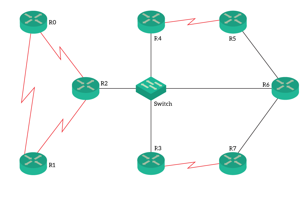
This is not a real-life best practice, as we have a single point of failure between R2 and the Switch. Anyway, this topology is perfect for learning purposes. To speed things up, we have already pre-configured the IP addresses. You can find more details in the following table.
| Router | Link | Address |
|---|---|---|
| R0 | R0-R1 | 10.0.1.1/30 |
| R0 | R0-R2 | 10.0.2.1/30 |
| R1 | R0-R1 | 10.0.1.2/30 |
| R1 | R1-R2 | 10.1.2.1/30 |
| R2 | R0-R2 | 10.0.2.2/30 |
| R2 | R1-R2 | 10.1.2.2/30 |
| R2 | Broadcast (Switch) | 10.2.100.2/24 |
| R3 | R3-R7 | 10.3.7.1/30 |
| R3 | Broadcast (Switch) | 10.2.100.3/24 |
| R4 | R4-R5 | 10.4.5.1/30 |
| R4 | Broadcast (Switch) | 10.2.100.4/24 |
| R5 | R4-R5 | 10.4.5.2/30 |
| R5 | R5-R6 | 10.5.6.1/30 |
| R6 | R5-R6 | 10.5.6.2/30 |
| R6 | R6-R7 | 10.6.7.2/30 |
| R6 | Broadcast (Switch) | 10.2.100.6/24 |
| R7 | R3-R7 | 10.3.7.2/30 |
| R7 | R6-R7 | 10.6.7.2./30 |
The Requirements
Since OSPF areas are beyond the scope of CCNA, in this lab everything will go in Area 0. Our goal is to configure OSPF routing using area 0 in all routers. While doing that, we need to specify the exact networks we are going to do routing for.
Furthermore, we will need to create a predictable OSPF system. As a result, we will need to configure specific Router IDs: 1.0.0.0 + the router ID. For example, R0 will have a RID of 1.0.0.0, while R5 will be 1.0.0.5. We also need to ensure that R6 is the master of the broadcast segment.
Configuring OSPF
The OSPF Process ID
After all, OSPF is a routing protocol just like RIP and EIGRP. Hence, it has its own config-router sub-prompt. Any router can run multiple independent OSPF instances, each identified by a process ID. Unlike many CCNA technicians may think, you don’t create a new instance for a new area. Instead, the same instance can manage all the areas you need. You will use different instances (processes) when you want to run two independent entities. They won’t talk with each other and don’t propagate routes between each other. Doing so is a CCNP topic that we don’t need to cover right now.
To create an OSPF process, you simply type the configuration command router ospf . In this command, the ID is a numeric identifier of the process itself. The process ID is a local value and doesn’t need to match between different routers. However, it is a good practice to simply use 1, and we will do for this lab.
Once you hit enter, you will enter the router-specific configuration sub-prompt. From there, you can enter all the OSPF-specific commands. This includes the definition of Router ID, authentication settings, and networks. We will see all of that later.
OSPF Configuration commands
Defining the router ID is simple. From the config-router prompt, you just need to type router-id followed by your desired ID. Cisco routers expect you to type a 32-bit number in dotted notation. In other words, what looks like an IP address (but that isn’t). Our lab has clear requirements for the router ID, so configure them accordingly. After defining the router ID, you need to reset all the OSPF neighborship to notify other routers. You can do that from privileged exec mode by typing clear ip ospf process.
The next, and most important step, is the definition of networks. By default, when you create an OSPF process, it won’t do any routing. This is because it is waiting for you to specify which are the networks involved in the routing. You specify them with the network command, followed by the network IP address, the wildcard mask and then area, followed by the area ID. In fact, with this command, you are not simply associating the network to the OSPF process. You are associating it with an area within the process. For this lab, all networks will go in area 0. (Tip: remember that the wildcard mask is the opposite of the subnet mask).
For this lab, we aren’t going to use passive interfaces. However, they are absolutely worth mentioning. When you add a network to the OSPF process, it will start to advertise it to the neighbors. And, it will also send OSPF hellos to find neighbors on that interface too. This is something we want if there is a known router connected to that interface. Instead, if the interface is facing toward clients, we might want to remain silent. We can do that by simply typing passive-interface in the “config-router” prompt, followed by the interface name.
A guided configuration
In the previous section, we condensed all the configuration commands you need for this lab. However, for the first configuration, we will guide you with a detailed explanation. Connect to R0 on the top left, and enter the global configuration mode. At this point, we type the following command.
router ospf 1You will see the prompt turning to R0(config-router)#. Silently, the router has created a new OSPF instance and an LSDB, which is empty right now. Before doing anything else, we need to define the Router ID. This is Router 0, so we will simply use 1.0.0.0, with the command below.
router-id 1.0.0.0At this point, the router will take the command but it may complain with the following error message.
Reload or use "clear ip ospf process" command, for this to take effectIf it does so, don’t worry. This means that some neighbors already know this router with a RID, and you are trying to change it. To make that change effective, you need to reset the relationship with the peers. To do that, simply type the following command (by remaining in the config-router prompt). It will reset the neighborships, and then try to form them back. Note that this can cause short disservice if you work in a real-life environment.
do clear ip ospf processType yes when asked, then continue with the configuration. At this point, we only need to define networks, with the following two commands.
network 10.0.1.0 0.0.0.3 area 0
network 10.0.2.0 0.0.0.3 area 0
We are simply associating the networks 10.0.1.0/30 and 10.0.2.0/30 to area 0. If you need a refresh on wildcard masks, simply check our ACLs article. This is it! You have now configured a router for OSPF routing.
Going on with the configuration…
All routers have a similar configuration. In fact, besides values (i.e. Router ID, specific networks) all commands are the same. Therefore, we don’t need a deeper explanation on them. Nonetheless, as a reference, we list below all the commands you need to use, for each router. Try to do the configuration on your own. If you don’t reach the 100% score, check the commands below to see what you did wrong.
This is R1…
router ospf 1
 router-id 1.0.0.1
 network 10.0.1.0 0.0.0.3 area 0
 network 10.1.2.0 0.0.0.3 area 0
Now, R2…
router ospf 1
 router-id 1.0.0.2
 network 10.0.2.0 0.0.0.3 area 0
 network 10.1.2.0 0.0.0.3 area 0
network 10.2.100.0 0.0.0.255 area 0R3:
router ospf 1
 router-id 1.0.0.3
 network 10.3.7.0 0.0.0.3 area 0
network 10.2.100.0 0.0.0.255 area 0R4:
router ospf 1
 router-id 1.0.0.4
 network 10.4.5.0 0.0.0.3 area 0
network 10.2.100.0 0.0.0.255 area 0R5:
router ospf 1
 router-id 1.0.0.5
 network 10.4.5.0 0.0.0.3 area 0
network 10.5.6.0 0.0.0.3 area 0R6:
router ospf 1
 router-id 1.0.0.6
 network 10.5.6.0 0.0.0.3 area 0
 network 10.6.7.0 0.0.0.3 area 0
network 10.2.100.0 0.0.0.255 area 0R7:
router ospf 1
 router-id 1.0.0.7
 network 10.3.7.0 0.0.0.3 area 0
 network 10.6.7.0 0.0.0.3 area 0
If you made it there, congatulations! You have now mastered OSPF. However, we still need to learn the tools to use when things go wrong.
Designated Router Election
Before diving into the configuration, we said that R6 should be the master of the LAN. In fact, it already is. This is because it has the highest router ID among all routers connected to the switch (R2, R3, and R4). So, it is the Designated Router, and R4 is its backup. However, there are some cases where we want to change the DR/BDR members. While doing so, we may want to not modify the Router ID.
We can do that by tuning the priority of the interface. To do that, just enter the configuration of the interface you like, and type ip ospf priority. You can specify the priority you want, between 0 and 255. The higher, the most the router is likely to be the DR. However, for this lab there is no need.
Troubleshooting OSPF
In this second part of this guide, we will learn how to troubleshoot OSPF. To do that, we will have a good overview of all the show commands Cisco offers us.
Logs of state changes
If you are in the console, or with the terminal monitor enabled, you can see when an adjacency changes state. Cisco will throw out a message that looks like this.
00:00:45: %OSPF-5-ADJCHG: Process 1, Nbr 1.0.0.6 on GigabitEthernet0/0 from LOADING to FULL, Loading DoneExcept on the LAN segment, we want to see everything going to the FULL state. The message above is the one you expect to see last.
Viewing the Link-State Database
To view the LSDB, we can type show ip ospf database. This command can yield a lot of output, and most of it is beyond the topics covered in the CCNA. Nonetheless, you will find handy being familiar with this command.
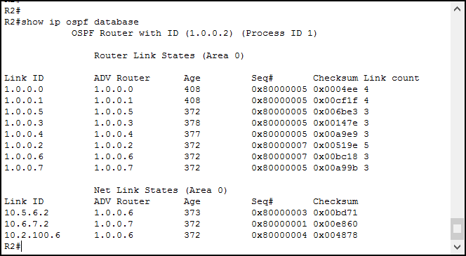
In case you have multiple OSPF processes, the router will show them separately in this output. As you can see, the output has two separate tables, but it can have more. In fact, the LSDB contains different types of Link-State Advertisements. Each type results in a separate table here. Even if 7 types of LSAs exist, in this topology routers are using just two.
The first table indicates Router LSAs. They represent a specific router and a related point-to-point link. You will see there all the Router IDs in the entire OSPF network.
The second table indicates the Multi-Acess network LSAs. We have three: the one on the switch, the one between R5 and R6, and the one between R6 and R7. Even if the last two looks like point-to-point, they are Ethernet interfaces. As a result, OSPF will treat them link multi-access network. Changing this behavior is possible by tuning the ip ospf parameters on the interface.
Viewing the neighbors
Configuring OSPF is fairly simple. Instead, the majority of problems come from adjacencies. Indeed, you need to assess if two routers are forming a neighborship. If they don’t, maybe something is wrong. To check that, you can use the show ip ospf neighbor commands.
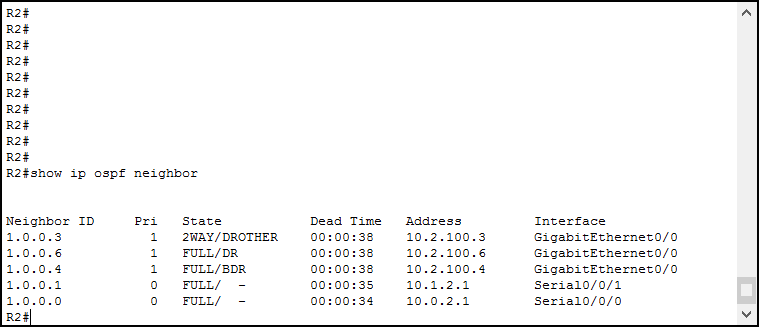
Well, Router 2 has a lot of neighbors. From this output, we can have a glance at all the neighbors. In fact, we can see their Router ID, their interface priority (if specified), and their state. Furthermore, we can see other useful information:
- The dead time indicates how many seconds will pass before the neighbor is considered dead; every time a hello is received this is reset to the default
- Instead, the address is just the IP address of the neighbor, on the interface facing toward our router
- The interface indicates the interface of the local router where we know the neighbor to be
The most important thing we want to see here is the state. We can see that column has two values, separated by a slash. We can see two separate states only on LAN segments because on point-to-point links only the leftmost state is shown.
On LAN connections (such as the first three entries), we see the state of the local router before the slash. After it, we see the role of the remote router. We can clearly see that we have a FULL adjacency with the DR (R6) and the BDR (R4). However, we don’t have that with R3. Instead, we have a 2WAY adjacency with it, because it is not DR/BDR, but DR-Other. Except with DROTHERs routers, we always want to see FULL adjacencies.
On point to point links, we only see the state and a dash after the slash. This is because no DR/BDR election happens here.
Conclusion
In this article, we have had the chance to do a real-looking OSPF configuration. We have learned all the commands we need, both for configuring and troubleshooting. With this knowledge, you are now able to deploy a medium-sized routing domain, which can contain up to 50 routers. This means you can potentially develop a nation-wide infrastructure! To do that, you need to remember the following commands.
router ospfto create a new OSPF instance, or configure an existing onerouter-idto customize the router ID, andclear ip ospf processto reset adjacencies and make the change go activenetwork <address> <wildcard> area <area id>to add networks to the OSPF routing process. You need to specify only directly connected networks, not remote ones. For the CCNA, always use area 0show ip ospf databaseto see the LSDB, andshow ip ospf neighborto see the adjacencies
We are gaining a solid knowledge of routing protocols. Now we have RIP and OSPF under our belt, but this is not enough. A real network engineer must know also about EIGRP, and possibly about BGP. This is what we are going to talk about in the next articles.

