
In the Enterprise, redundancy is simply a must. With the previous article, we have seen how HSRP allows fault-tolerance on the default gateway. Now, it is time to get our hands on these technologies and configure some devices for them. In this article, we will see how to implement the Hot Standby on two routers, and learn all the related commands.
Since this article sees you doing some configuration, it comes with a Packet Tracer lab. You can download for free the file using the link below, then open it with Packet Tracer.

Once you do that, you can continue reading the article with the lab opened. You will be able to try every command we explain, the moment of the explanation. With this approach, mastering HSRP will be extremely easy.
Configuring HSRP Lab Intro
The Topology
Our major focus for this lab will be HSRP. To avoid distractions, we will use only the devices we need, as in the picture below.
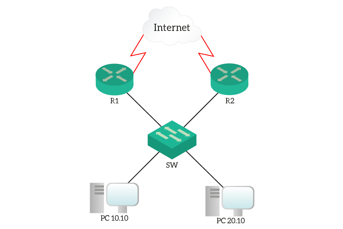
We will implement HSRP on two routers, R1 and R2. Those will be doing Hot Standby on two VLANs, one containing PC10.10 and the other containing PC20.10. We also connected the routers to a “fake Internet”, where we can use the 8.8.8.8 address to test ping and traceroute.
The Requirements
We are going to use HSRP to complete a gateway redundancy configuration. We have different VLANs, 10 and 20, so we will need to configure two virtual gateways: one for each. As a requirement, in normal condition, R1 should host the gateway for VLAN 10, and R2 the one for VLAN 20. However, upon failure, the other router needs to take over the load of its peer. In case the failed router is restored, we want it to take back its own load, as in the normal condition.
To these basic requirements, we will add a fine-tuning. Our routers use two serial uplinks toward the Internet. If that link on a router fails, we don’t want it to be the master. If it is, devices will send traffic to it, but it won’t be able to forward to the Internet. Instead, if the uplink fails on a router, we want to trigger the HSRP swap, like if the router failed.
Configuring HSRP
Before we start…
Before we start with the configuration, take a moment to look at the existing configuration on the devices. We already created the two VLANs and put the PCs in them. However, the part of the configuration that grabs our interest is the one on the routers. As we learned in the Router on a Stick article, we are using subinterfaces. This way, we can connect a single cable with an 802.1Q trunk and have multiple VLANs on it. As a result, we can also have multiple IP addresses (one per subinterface, which is a VLAN).
VLAN 10 is the network 10.0.10.0/24, while 10.0.20.0/24 is VLAN 20. In both VLANs, the IP address of R1 is .2, and the one of R2 is .3. Why would we do that? Because we need to reserve the .1 address for the Virtual Default Gateway.
Our first HSRP Configuration
Configuring HSRP is easy. The first thing we need to do is enter the configuration mode for our interface. When configuring HSRP, you need to define groups. A group is just a set of configuration commands tied with one another, and that creates a single Virtual Gateway. Cisco identifies these groups with a number, and as a best practice, we should always use the VLAN ID.
All HSRP-related commands start with standby <group id>. Using this command, we will need to define interface Virtual IP, priority, preemption, and any other option.
As a first step, we need to define the IP of the Virtual Gateway. To do that, we can use standby ip <address>
. After entering that command, the router will create a Virtual Gateway. If it doesn’t find any other HSRP, that virtual IP address will go active on this physical router.
Then, we can define the HSRP priority with standby <ID> priority <value>. HSRP peers use priority to select which physical router should go active on the virtual IP address. The higher the priority, the more likely the router to go active (default is 100).
And, finally, the preemption. If a router is preemptive and has a higher priority than the currently active router, it will trigger a re-election process. For example, if the primary router has a power outage, the secondary takes its load. When that router comes back, however, it will be active again. This is something we might want, or not. However, this is a requirement for this lab and we will configure it. To do that, we just use standby <ID> preempt.
Configuring HSRP on Router 1
Based on what we learned in the previous section, we can now configure HSRP. We will start on R1 in VLAN 10, so we will use its GigabitEthernet 0/1.10. In there, we need to specify the Virtual IP of the gateway, which is .1. We also want to use a priority of 101 and turn on preemption. All of that for VLAN 10, so we should name the HSRP group “10”. Below, all the commands.
interface GigabitEthernet0/1.10
 standby 10 ip 10.0.10.1
 standby 10 priority 101
 standby 10 preempt
At this point, you might see some Syslog messages telling that HSRP configuration went active. Don’t worry about them for now, we will explain them when it comes to troubleshooting.
Our next step is the configuration of VLAN 20, mapped on GigabitEthernet0/1.20. For that VLAN, we always need to use the .1 IP address, and enable preemption. However, since this router shouldn’t be active for that VLAN, we won’t configure priority (leaving it at default). So, here’s what we need to type.
interface GigabitEthernet0/1.20
 standby 20 ip 10.0.20.1
 standby 20 preempt
Configuring HSRP on Router 2
Router 2 is specular to router 1. It must be passive (standby) for VLAN 10, and active for VLAN 20. Therefore, we need to enter almost the same commands, but for different interfaces. In fact, Router 2 uses GigabitEthernet0/2 and its subinterfaces.
For VLAN 10, we will do this:
interface GigabitEthernet0/2.10
 standby 10 ip 10.0.10.1
 standby 10 preempt
And, for VLAN 20, we will do this instead:
interface GigabitEthernet0/2.20
 standby 20 ip 10.0.20.1
 standby 20 priority 101
 standby 20 preempt
Now, our basic HSRP configuration is completed. We have an effective setup that makes the default gateway effectively resilient.
Interface tracking in HSRP
HSRP supports an easy way of doing interface tracking. In other words, we can configure HSRP to monitor an interface on the router. If that interface fails (goes down/down), HSRP automatically decrements the priority of the router. This can cause the Virtual Gateway to move to a different physical router.
This is something we want for our setup. In case our uplink fails, we want the other device to be active because it is the only one with an active uplink. This is also very easy, we simply need to type standby <ID> track <interface>. By default, it will decrement the priority by 5 in case of failure. In real world (not in Packet Tracer), you can also change that value.
Here’s what we need to type on R1 (affects both VLANs):
interface GigabitEthernet0/1.10
 standby 10 track Serial0/0/0

interface GigabitEthernet0/1.20
 standby 20 track Serial0/0/0
And on Router 2 (still affects both VLANs):
interface GigabitEthernet0/2.10
 standby 10 track Serial0/0/0

interface GigabitEthernet0/2.20
 standby 20 track Serial0/0/0
Congratulations! Your lab is now completed, and you should have reached a 100% score. Now, it is time to learn how we can verify and troubleshoot HSRP.
Verifying and Troubleshooting HSRP
Who is my gateway?
On any client device, you are going to use the Virtual IP as a default gateway. As a result, you don’t know which physical path you are taking. However, we want to know that in a very deterministic way. Luckily for us, Cisco implements a very simple way to tell which physical router we use.
If you just make a traceroute, you will see the list of hops in the path. However, as a first-hop, you won’t see the Virtual IP. Instead, you will see the IP address of the physical router currently active. This is because traceroute works with the TTL timeout, and when the Cisco router has to send the “TTL Expired” message, it sends it from its own IP address. Here we have the two examples.
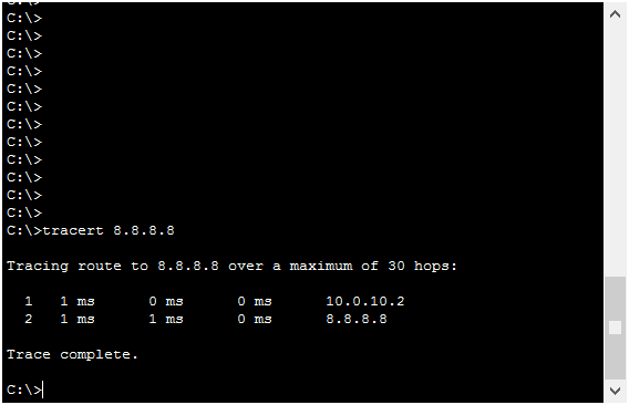
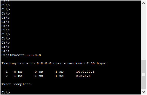
Now, don’t look at the subnet. It is obvious that PC10.10 will have a next-hop in the 10.0.10.0/24 subnet, and PC20.10 in 10.0.20.0/24. Instead, look at the last digit. It is not .1, but .2 in the first case and .3 in the second. If you remember, at the beginning we stated that .2 identifies always Router 1, and .3 identifies Router 2. This means one thing: our HSRP is working!
Syslogs on modification
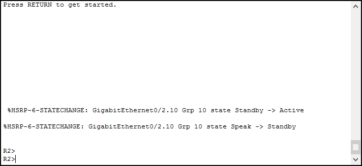
If you are working in console on a router, or you if you turned on the terminal monitor on VTYs, you can see Syslog messages. These are notification messages of what’s happening on the router. Well, in case the router becomes active (or goes standby) for HSRP on a VLAN, you will get a Syslog message. They look like these:
Each message tells us some interesting facts:
%HSRP-6-STATECHANGEtells that this is a Syslog about HSRP, and it is just an Information (level 6). It also specifies which kind of event happened, a change of state.GigabitEthernet 0/2.10is the interface where the router has seen the eventGrp 10is the HSRP group affectedStandby -> Activemeans that the router went active,Speak -> Standbymeans that the router stopped being active for that VLAN
Interestingly, we caused this change of state by turning off and on the Serial interface on Router 1. Thanks, interface tracking!
An overview of HSRP
Like in many other cases and protocols, our best companion is the show commands. To see the all-in-one summary of HSRP, we can simply use show standby brief. Here’s an example.
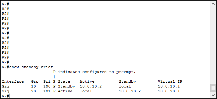
This output is a simple table, telling us a list of interfaces where we configured HSRP. For each, we see which groups are active, and which is the local priority on that group. We also see a “P” indicating the preemption. Then, we have some dynamic data.
State indicates what is the role of the physical router in this moment. Active means that it is using the virtual IP, standby that it isn’t (someone else is). If the state is active, the command tells the IP of the active router. Otherwise, it tells the IP of the standby router that will succeed this one in case it fails. In the end, we see the virtual IP.
A more extensive output
If you want to see more information, you can simply run show standby. We can also trim this command for a single interface by typing its name. Here’s an example.
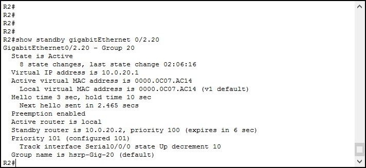
These commands add some static and dynamic information. We can see how many times the state changed, and when it did so the last time. We can also see the virtual MAC address and some information about timing and priority.
Conclusion
In this article, we learnt how to configure HSRP on Cisco devices. If you already understand how HSRP work, you just need to take with you the commands from this article. For your convenience, here we have the must-know ones.
- Use
standby ip <address> - Set priority with
standby <ID> priority <value>, default is 100 - Enable preemption with
standby <ID> preempt - Track interface status with
standby <ID> track <other interface name>, this will reduce the priority if that interface is down - Verify with
show standby, eitherbriefor followed by the interface name
Once you feel confident with these commands, you can move to the next article. Continuing the CCNA course, we will see how to enhance security at the access layer. After that, we will dive into routing at a deeper level.

