
Believe it or not, you could make an enterprise collapse by plugging a cable in the wrong place. In fact, a wrong connection may cause a loop with frames duplicating across the network. The Spanning Tree Protocol (STP) prevents just that. In this article, we will learn how STP prevents loops, and how it handles the Layer 2 convergence. Having a solid knowledge of STP (IEEE 802.1D) is a mandatory requirement for any networker.
This article heavily relies on your switching knowledge. In case you don’t have any or need a refresh, you can check out our Data Link layer article.
Introducing Spanning Tree
The need for STP
From the introduction, we already know that STP is out there to prevent loops. However, we haven’t explained what those loops are just yet.
A loop is a series of switch connections that allow a frame to get back where it started.
So, if a computer generates a frame and sends it to a switch, and the frame gets back to that switch at some point in the future, we have a loop.
This is common for broadcast frames, that a switch sends to all ports but the originating one. If we have three switches forming a loop, like in the picture below, without Spanning Tree broadcast frames will loop.
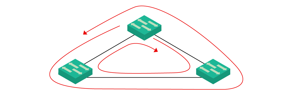
Now, we want to have multiple connections between switches for redundancy. This way, in case one link stops working, we can have an alternative path. However, this inevitably creates loops, which are dangerous for broadcast frames. In the next paragraphs, we will see why.
Broadcast Storms explained
Imagine a computer connected to the top switch generates a broadcast frame. The switch will send the frame to all its clients, and to the two other switches as well. Then, the switch on the left will send the frame to the switch on the right, and vice versa. Now bad things start to happen. The switch on the right takes the switch received from the left switch, and send it back to top switch. Meanwhile, the left switch does the same with the frame from the right switch.
They are all the same frame, but the two bottom switches have no way to tell. At this point, the top switch receives two frames, and it can’t know they are duplicates. Therefore, it sends the two frames again (the one received on the left to the right, and the one received on the right to the left). These frames will continue to loop on the network until a switch crashes and the ring is opened.
This happens with Layer 2 broadcast frames, including ARP requests, which are broadcasts. As a result, networkers named this behavior Broadcast Storm. In a complex topology, frames may even duplicate, creating more and more identical frames on each loop. This is a sure way to make your switches crash.
How STP Prevents loops
Now that we know the problem, we need to know the solution. Before diving into Spanning Tree operations, and learning how it works, we need to know what it does. It is now clear that it prevents loops, but what does this mean exactly? Spanning tree blocks links, so that frames received on a blocked link are discarded. We can take the previous example of the three switches in a triangle topology. The spanning-tree would make the topology look as below.

We can see that now the top switch can send frames to the left and right switches. However, the right switch will never send traffic on the link with the left switch. In case the right switch receives traffic on that link, it will simply drop it. We have no loop. Even if the left switch needs to talk with the right switch, they will make the traffic pass through the top switch.
Spanning Tree is on by default in all Enterprise switches. You can’t even turn it off, as it is a key feature that will save your network. For no reason, you might not want it. Nonetheless, our job as Network Engineers is to tune STP to act the way we want. Our ultimate goal is to define which links to blocks, and what available paths to use. The next sections are just about that.
Spanning Tree Operation
The basics of STP
In this part of the article, we are going to cover all the basic features of Spanning Tree, and explaining its terminology.
Everything starts from the Root Bridge
Spanning Tree was originally designed for Bridges, the predecessors of switches. Now bridges are legacy components, but the STP jargon didn’t change. Therefore, when we talk about a bridge we really mean a switch, for all STP-related topics.
Ideally, STP has kept active the best link (shortest paths) and block suboptimal links. To do that, it needs to define which switch is in the center of the network. This is the root bridge, which is going to have all ports active. Then, STP builds the entire topology keeping that root bridge in the middle.
STP identifies each switch with a numeric ID, called Bridge ID (BID). This is a binary number that we can divide into three parts. The first 4 bits are admin-customizable and indicate a priority level for the switch. Then, we have 12 bits to indicate the VLAN, so that each switch can use different priorities for each VLAN. Finally, we have 48 bits to put the MAC address of the switch.
The Bridge ID is used as a major tiebreaker for any STP process, including root bridge selection. You can tune it by changing the priority part of it. If you don’t, with everything set to default, the MAC address (as part of the BID) will be used.
Spanning Tree Ports
Spanning Tree sees each port (interface) in three possible ways: root, designated, and blocked.
- The Root Port is the port a switch is using to reach the root bridge. You can see this as an uplink; the root bridge won’t have any as itself is the root, while each other switch will have one (and only one). The root bridge doesn’t need to be directly connected on that port, you might encounter intermediary switches as well.
- The Designated Port is an interface a switch uses to give connectivity to non-root bridges. This is a downlink, all switches reachable through this port will need to pass from the current switch in case they want to reach the root. The root bridge itself will have all its port into the designated state.
- Spanning Tree decides to close some links: those are called blocked ports
With this in mind, you are ready to see how switches talk with one another to span the tree.
Bridge Protocol Data Unit (BPDU)
To converge, switches need to talk and exchange information. They do it with a special frame, the Bridge Protocol Data Unit, or BPDU. You can think of it like the STP frame because it contains STP-specific information. Switches do not forward BPDUs, they read them and learn information from them. Then, with this new knowledge, they may start sending different BPDUs. Each switch sends BPDUs out of its interfaces once in a few seconds. Each BPDU contains:
- The Bridge ID of the switch that created the BPDU
- The Bridge ID of the root bridge, according to the current switch’s point of view
- The cost to get to the root bridge if passing through the switch that originated the BPDU. The lower the better
By checking the BPDU of each other, switches can elect the root bridge in a network.
Root Bridge Election
The first thing STP does is the election of the root bridge. To do that, each switch starts to send out BPDUs claiming to be the root bridge. As you can see in the picture below, those BPDUs have the Bridge ID and the Root Bridge ID fields identical. They also indicate a cost of zero, because each switch can reach itself with no cost.
Note: To keep things simple, we represent Bridge IDs with 4096, 8192, and 32768 only. These are the values of the priority field, but in reality, we should also consider VLAN ID and MAC address.

For the root election, the lower the Bridge ID the better. Switches will check the root bridge they receive, and if they had a higher one they will erase that and start sending BPDUs with the newly discovered Root Bridge ID. Meanwhile, they switch the port where they received the BPDU to be a Root Port.
However, since the root bridge is now a remote switch, and not the switch itself, the cost can’t be zero. To calculate the cost, the switch takes the cost received in the BPDU (zero in this case) and adds the cost of the root port. The cost of a port depends on its bandwidth, as in the table below.
| Bandwidth | STP Cost |
|---|---|
| 10Mbps | 100 |
| 100Mbps | 19 |
| 1Gbps | 4 |
You can tune these costs on each interface if you need to.
Blocking the ports
Now we might want to take a look at what happens between the left and right switches. The left switch agreed with the top switch that top switch is going to be the root and starts advertising top switch as the root bridge. However, right switch is going to do the exact same thing, and we need to close the loop.

The switch on the left receives a BPDU with identical root bridge and cost to the ones it already knows. So, it checks the Bridge ID field, which is higher than its own. Because of that, it keeps the port facing the right switch in the designated state. Meanwhile, the switch on the right checks the BPDU of the left switch. Everything is identical but the Bridge ID, which is lower. Since the right switch understands to have a higher Bridge ID, it is the one that blocks the port, on its side.
At this point, we get back to the picture we showed previously, with the link between Right and Left switch blocked on the right side.
We define “Superior BPDU” a BPDU with a lower Root ID. It is superior because it is the most preferred for the root election, but in reality, Root Bridge ID is lower.
Other STP Concepts
At this point, you would have a clear understanding of the role STP has in a network. We can now dive into some fine-tuning concepts and settings that will help you stand out in your networking job.
STP Port States
Back in the previous section, we defined that a port can be root, designated, or blocked. The truth is, root and designated are two port roles, while blocking is a state. However, we have also other states. Each port has both a role and a state. With the STP algorithm, the ports evolve into different states as in the following diagram.

Each state has specific functions and characteristics.
- Initialization, formally Boot-up Initialization, is the beginning state. The switch is booting, and the interface isn’t ready just yet.
- The blocking state is the first one. STP starts will all ports in blocking state, and later move them to other states. In this state, the port doesn’t participate in frame forwarding: it doesn’t send frames nor listen to the ones received. However, it still listens for BPDUs.
- After the blocking state, we have the listening state. If STP decides that a blocking port may be activated, the switch moves the port into listening state. This state is essentially like the blocking state, but the switch starts to send out BPDUs.
- Then, we have the learning state. After a given timer, the port transitions from listening to learning. It sends and receives BPDUs, but it still doesn’t participate in frame forwarding. However, it learns the MAC address of the frames it receives, even if they are discarded. The port is getting ready to go into forwarding.
- Finally, the port in the forwarding state sends an receives frames and BPDUs.
- A port is in the disabled state if the administrator (or Cisco IOS) shut it down for other reasons
All “Root Ports” are in forwarding state.
Spanning Tree Instances for VLANs
Spanning Tree is great, but you won’t see any plain STP (IEEE 802.1D) out there. This is because it doesn’t consider the existence of VLANs. STP BPDUs aren’t encapsulated into tagged frames, so there is no way to consider VLANs. Fortunately, Cisco has designed the Per-VLAN Spanning-Tree (PVST) which considers them. To do that, they reserved 12 bits from the priority field to insert the VLAN ID. This way, we have 4 bits left to tune priority, and 12 to differentiate between VLANs.
As a result, a switch may be the root bridge for a VLAN, but not for the others. The advantage of doing that is clear when you have multiple VLANs: you can load-balance traffic so won’t all go to through the same switch.
What if a switch fails?
Spanning Tree is dynamic, and can converge. It readapts to topology changes, but it might be not so clear how can it do so. The network needs to converge again in case either the root bridge fails, or some switch with at least an active designated port (connecting other switches with higher BIDs) fail.
The switch directly “under” the failed switch notices that its root port isn’t working as expected, because it doesn’t receive BPDUs. At this point, it simply starts again to believe to be the root bridge. Other switches with lower bridge IDs will calm it down, telling they have another path to the root. In case the root failed, a new election takes place.
Depending on the severity of the failure (root bridge or peripheral switch), the downtime may affect all or only some switches.
Spanning Tree is Slow
Yes, you read it right. Spanning Tree is an extremely slow protocol. Routing protocols converge in less than a second, while STP needs 50 seconds. This is because it needs to move each port through all the states before it starts forwarding. By default, it needs to stay in each state for 15 seconds (on Cisco switches).
The reason for that is to allow information to propagate over the entire switch domain so that even far-away switches have the time to be included in the calculation properly. Tuning timers may be a good idea to speed things up, but this is an advanced topic.
However, there are some ports you know for sure aren’t going to connect switches. You know they are going to connect only clients. On them, you can use a great Cisco feature known as PortFast. That features allow the port to transition to the forwarding state immediately. However, if you then connect a switch to that port STP won’t be running on it. You can cause loops, and shut down your network. To use PortFast in safety, you can associate it with the BPDUGuard feature. This feature immediately shut down the port if a BPDU is received. This way, you can safely turn on PortFast for all of your clients (PC, Servers).
Modern networks implement different technologies that reduce the need for STP, acquiring better results in less time. However, we will still need to run STP on edge ports (the one connecting clients). This way, in case a user attaches an unmanaged switch and creates a loop, we can protect the network.
Conclusion
In this article we presented this huge beast of networks, Spanning Tree Protocol. By knowing it, you are building a great skill set that allows you to work on Enterprise-level architectures. Here we quick list of things you absolutely need to remember.
- STP protects you from broadcast storms by blocking some links in the network
- Switches send out BPDUs to agree on Spanning Tree information: each contains the root bridge ID, the current switch bridge ID, and the cost to the root. Ultimately, the switch with the lowest bridge ID will become the root bridge, and the best paths to it (with the lowest cost) will remain active
- The port facing to the root is the root port, the ports facing to peripheral switches are designated port
- You can tune the bridge ID by configuring its priority. It also considers the VLAN ID, that allows you to have different STP topology (one for each VLAN)
- Spanning Tree is slow to converge (50 seconds) because each port needs to transit between blocking, listening and learning state before forwarding
With this knowledge, you are now ready to configure and troubleshoot STP on a network of Cisco switches. This is exactly what we are going to do in the next article in the CCNA course!


2 Responses
Alessandro, Awesome article and an amazing site. I love it! Is been awhile since i actually studied STP; this was a great refresher. Next article, is the GRE and OSPF.
keep it up! i will make sure to spread the word about this site. Thanks for taking the time to put this together.
Malik, thank you so much! I am so happy to be of such help, and your comment really motivates me. I will keep up, for sure!
And thank you for spending your time spreading the word about this site! I really appreciate it!!
Comments are closed.