The transport layer is sitting on top of the network layer and serves directly applications: while the Network Layer allow the delivery of information between two computers anywhere in the Internet, the Transport Layer allows the communication between two applications on two different computers. In this article, we will discover how is this possible, then we will have an high-level overview of the two most important protocols we can find in this layer: TCP and UDP. Let’s get started!
Transport Layer means Application-to-Application connections
If you are following the CCNA course, you should know pretty well the network layer from the previous three articles (IPv4 addressing, IPv4 subnetting and IPv6), and you know that it allows two remote computers to communicate over the network. If you look at the reason behind two computers communicating, you will find out that they are actually communicating in order to allow the application running on them to communicate. All the traffic is sourced from an application and destined to another application on another computers: think about what you do with your computer, you are extremely likely to surf the web, watch online video – using a web browser for that – or make VoIP calls. for instance, with Skype. These applications require Internet access to talk to their server, a computer somewhere in the Internet providing the content you are asking for. For Internet surfing, the server is the computer containing the web page you are looking at, and that sends that web page to you whenever you ask; for YouTube, it is the computer sending you the video you are watching, frame after frame, while for a VoIP call is the computer of your friend you are in a call with that is sending audio to you.
All of these communication happens over the Internet, and for your PC is fairly easy to send out traffic for the right destinations. However, when the reply traffic comes back, the computer has to deliver it to the right application, and only to it, so that each application can see only its own traffic. Doing that can be easy while we are talking with separate servers; if that’s the case, then we can know that a given server is interfacing with a specific application, while another application is talking with another server, just like in the picture below.
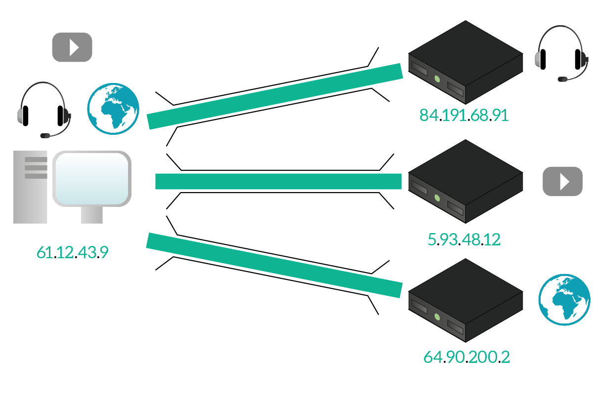
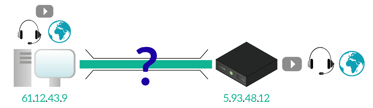
This is great, but we cannot assume that each application is going to talk with a separate server dedicated only to that. For example, YouTube is a website containing video, how can you identify and differentiate the web-page traffic from the video itself? This may become harder when you are talking to a single server for multiple applications, so we cannot rely on having always separate IP channels (different destination servers).
The Transport layer has been designed specifically to solve that problem, and it does that in a terribly simple way. At the transport layer, we give an address to every application that wants to communicate over the network. That address identifies uniquely the application within the computer, and it is a 16-bits integer named Port ID. That number can go from 0 to 65,535; the application can ask to have a specific Port ID but is the operating system of the device that has to ensure that this Port ID is not being used from another application. With that identifiers, we are able to keep traffic of different applications separated.
Tip: “Port ID” is simply called “Port” most of the time.
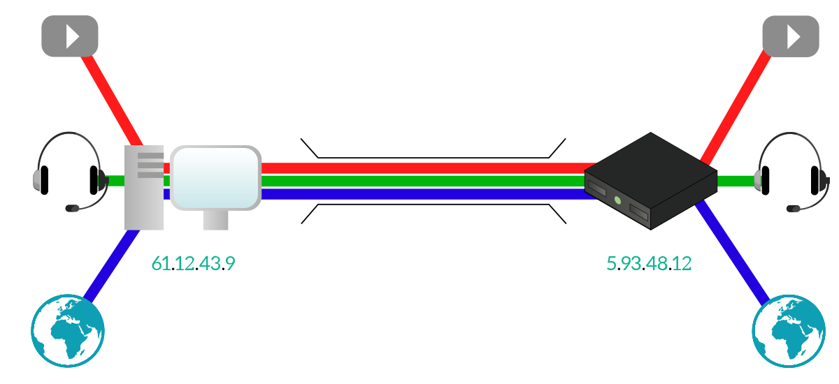
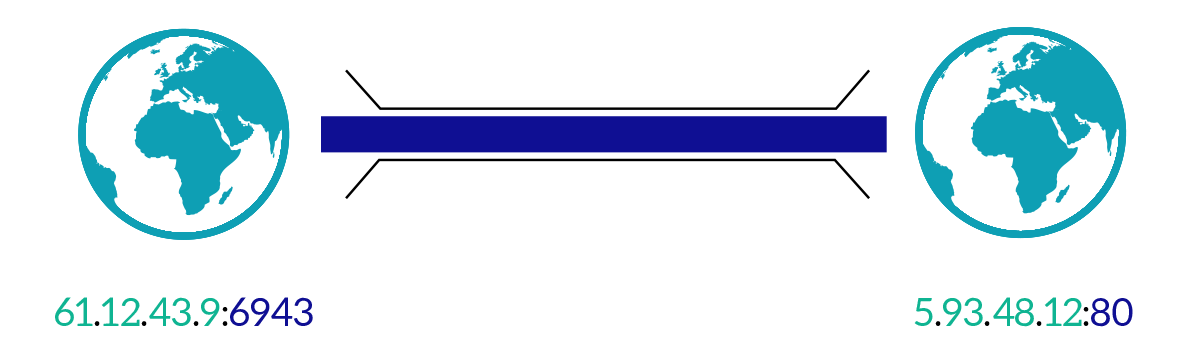
Considering that the Port ID is unique only within a computer, it can be used only from the computer itself: when the computer receives an IP packet from any other device, it will send the payload to the right application based on the Port ID. However, the delivery from a computer to another is still based on IP routing. Based on that, the Port ID can be used to uniquely identify an application on a computer, while a public IP address can be used to uniquely identify a computer on the Internet. This means that the combination of IP address and Port ID uniquely identifies an application over the Internet. That combination of IP address and Port ID is technically known as socket: two sockets together uniquely identify the communication between two applications over the Internet.
Since the Port ID is an integer, it is represented as a decimal positive number, and when we have to write down a socket we just write the IP address and the Port ID, separated by a colon. This is easy in IPv4, as we the IP address is written in dotted notation (e.g. 10.10.10.91:80), but it might become more complex with IPv6 since it already contains colons. In that case, we use square brackets to separate the IPv6 address from the Port ID as follow: [2001:db8:acad::12]:80.
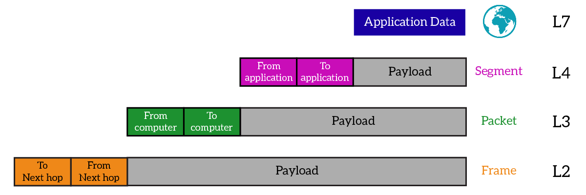
We already know that the concept is pretty simple: giving an identifier to applications to keep traffic separated. However, we don’t know just yet how is this implemented. You might guess the answer, the application (such a web browser, a game, Skype etc.) passes its data to the Transport layer, where some extra items are added. The application data, plus the items added at this layer, from the Transport Layer Protocol Data Unit (PDU), which is known as Segment or Datagram. The header of the segment is different if the protocol used is TCP or UDP, but no matter what protocol is used, two items are always present: source Port ID and destination Port ID. They are just what the name says they are, the source Port ID identifies the application on the device that created that segment, while the destination Port ID identifies the application on the device that this segment is destined to.
Just like with IP addresses we had some specific private addresses, public addresses, and multicast addresses, with Port IDs we have some specific ranges: not all applications can use the same Port IDs. Specifically, we can divide Port IDs into three ranges: well-known ports, reserved ports, and dynamic or private ports. The purpose and details of these ranges are contained in the following table.
| Range Name | Ports in Range | Description |
|---|---|---|
| Well-known | 0-1023 | Ports in this range are used for popular services (such as HTTP, FTP, DNS, etc.) and are generally used on the device providing the service (the server). |
| Reserved | 1024-49151 | Ports in this range are used for service applications (the ones running on servers), but that was added later the well-known number or for proprietary service (you can purchase from IANA your own port ID). Sometimes ports in this range are used as dynamic (see below). |
| Dynamic | 49152-65535 | Ports in this range are used by the client application as they do not need a specific Port ID, but instead, just any port to be able to make requests to servers: a client application will dynamically use a random Port ID from this range. |
Now that we know the logic of the Transport layer, and its most important component (the Port ID), we can focus on what the two most used protocols at this layer – TCP and UDP – add to the mix, their advantages and disadvantages.
TCP at a glance
Overview
The first protocol we should check out is TCP, which is the acronym of Transmission Control Protocol. This protocol has been the undisputed king of this layer in the past decades, it is the most complex and feature-rich one. This protocol has been designed with a major goal: ensure a reliable delivery of data between remote applications. Let’s take a look at its characteristics.
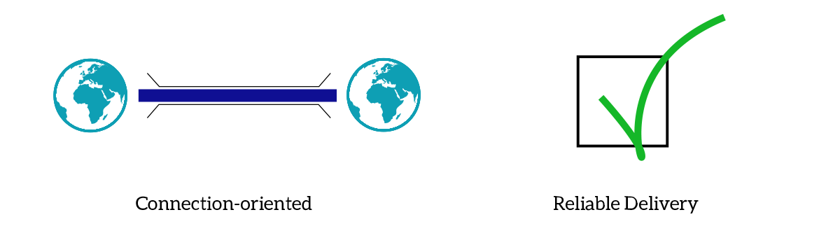
As we can see from the picture, TCP is a connection-oriented protocol, which means that the two application must establish a connection before they can actually start to send data to one another. This means that they have to agree they should communicate before they can do it. By having a connection, we can then use it to control the data transfer in order to grant reliable delivery of data. This mean that when information is sent, it is granted that it will be received from the application on the other side. This is possible because the receiver notifies the sender when it receives data and, in case it doesn’t, there is a mechanism that triggers the sender to re-transmit data that was not received. But features do not end here, TCP is also able to grant ordered delivery (data arrives in the order they were sent, if not they are reordered by the receiver) and reduce transmission speed based on the congestion of the network.
TCP Header
All these features are possible thanks to the implementation of TCP with a dedicated header in the segment and with specific algorithms that run on the computer that is using TCP to talk. These algorithms read and set the fields in the TCP header based on some logic we will explain later on in this article, but before we can get to that we have to skim the TCP header itself.
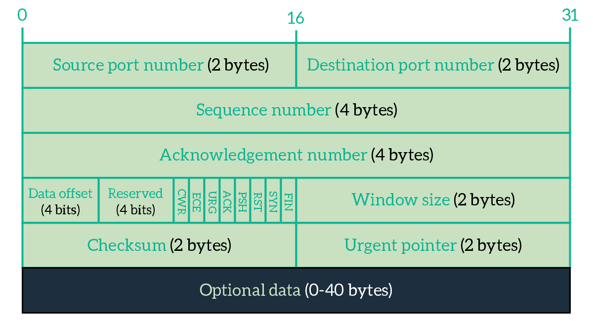
TCP is an extremely powerful yet complex protocol. Explaining all of its features here is out of the scope for this article, so the next article in the CCNA course will be dedicated to all the details of TCP. For now, we will explain only the fields that allow you to understand how TCP works at a high level.
- Source Port – Identifies the application on the device that sourced the current segment.
- Destination Port – Identifies the application on the device that will receive the current segment.
- Sequence number – In TCP, we send a stream of bytes. This field is an integer that identifies to which byte in the full stream the first byte of the TCP payload corresponds to.
- Acknowledgment number – This field is an integer used from the receiver to tell the sender that it has received some data. It is populated with the byte number the receiver expect to see next after what it already received.
- Flags – These flags are 1-bit long fields used to set specific parameters of the connection
- ACK (Acknowledgment) – Set to 1 from the receiver to tell the sender to check out the Acknowledgment number field
- RST (Reset) – Inform the other device that the connection is being closed immediately (hard reset of the connection)
- SYN (Sync) – Used to establish a connection
- FIN (Finish) – Used to gracefully close a connection
- Checksum – Hash/Summary of the entire segment used from the receiver to verify that no errors happened during the transmission
Knowing these fields, we are ready to explain how TCP works and how it implements its most basic features, plus we will be ready to understand the complex ones in the next article.
Establishing the connection
We already said that TCP is connection-oriented, now it is time to see how it actually establish a connection. This is down with a procedure called three-way handshake, because it involves three exchange of data. In this procedure, one device wants to talk to another and initiate the connection to it by sending an empty TCP segment with the SYN flag set to 1. This segment contains basically only the source and destination ports and that flag set. Most of the time, the device initiating the connection is the client (the one asking for services). If the device on the other side as an application listening to the specified destination port, and if that application is willing to respond to that device, it will back an empty segment with the port IDs specified, the SYN flag set to 1 and the ACK flag set to 1. By doing so, the device is telling to the initiator that it got the request, and it is also willing to open the connection. At this point, the device that originally initiated the connection, send back a frame to the other device with the ACK flag set to 1. After that, the connection is successfully established and the two device can start to exchange data. The following picture shows just that.
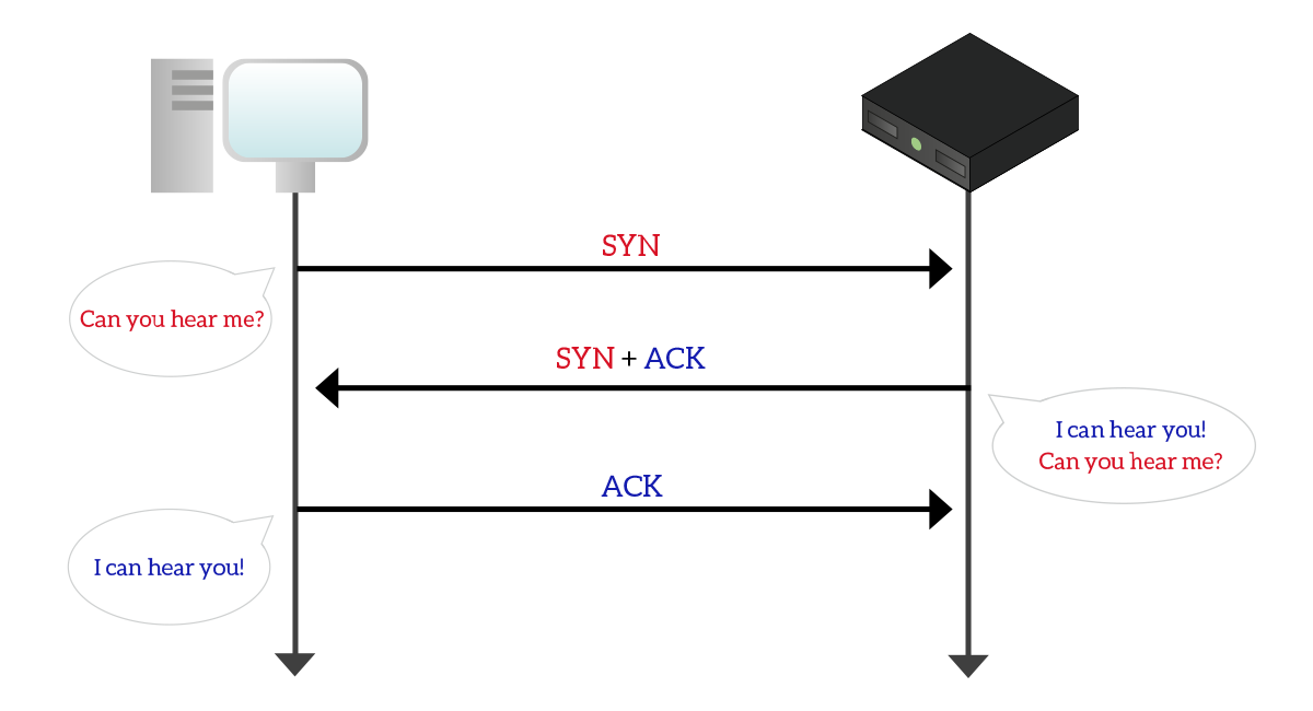
Obviously, source port and destination port in segments sent by the client will be the destination port and source port in reply segments sent by the server.
The data transfer
Once the connection is established, the true data exchange starts, and the reliable delivery goes with it. This feature, which comes with ordered delivery, relies on two fields in the TCP segment header: sequence number and acknowledgment number. Applications see TCP connections as streams of bytes, so they can tell how each byte received is located in the entire stream. With that concept in mind, when an application is sending data to another, the sequence number is used to tell what is the position of the first data byte being send (the first byte of the payload) in the entire data stream. Let’s say we have to send 1,000 bytes, but we can send only 100 at a time. The first sequence number is going to be 0, the second 100, the third 200, and so on. This has a simple and immediate use: it allows the receiver to reorder the segments in case it receives them in the wrong order (maybe some of them took a different path over the network that was either faster or slower). The sender, however, can send a limited number of bytes (even in different segments), but after that it has to stop and wait for the receiver to acknowledge them, to tell that it actually received the segments. This is the purpose of the acknowledgment number field. It is used from the receiver to tell the sender what is the byte is expecting (of the entire flow). This implies that all the bytes before this one were received correctly, for example, if the acknowledgment number is set to 800 it means that bytes from 0 to 799 were correctly received. The following picture explains this procedure in a visually.
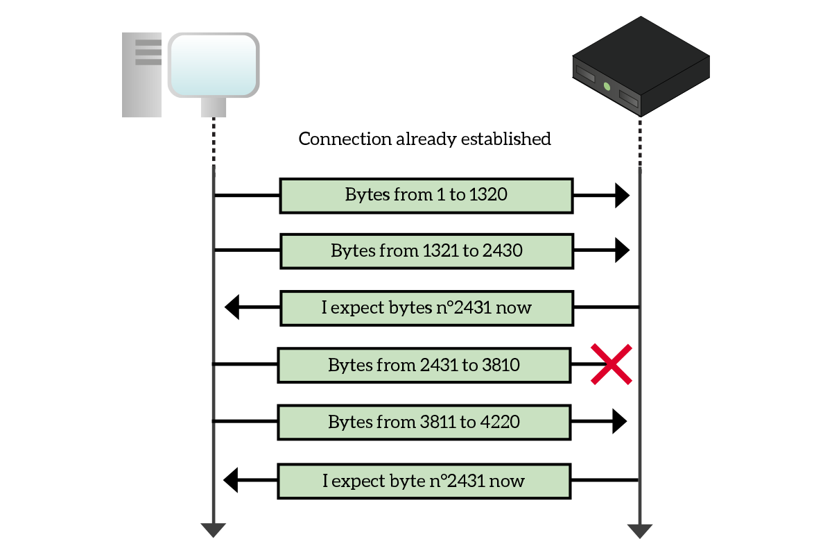
As the picture highlights, in case the receiver has missed a segment but the next one was correctly received, the receiver will send back to the sender an acknowledgment number that allows the retransmission of the missed segment, this way all the received segments after that will be discarded. This is not the optimal behavior, but it is the one used in the most basic implementations that do not rely on Selective Acknowledgment, which is beyond the scope of this article. Note that retransmission is triggered in three cases: when the receiver does not receive segments, when the sender does not receive acknowledgment segments (it assumes that sent segments were not received after a timeout expired), and when the receiver verifies that the checksum do not match the segment.
From what we have seen until now, we might think that TCP allows data to be sent in one direction only, but this is not the truth. A TCP connection allows bi-directional data transfer, and this means that there is not actually a sender and a receiver, but instead, each device will send to the other data with an increasing sequence number and expect acknowledgment numbers from it. To put that very simple, in a segment a device says “Hey, I am sending you byte 3,200 of my stream. I am expecting byte 1,800 from your stream”. Sequence and acknowledgment numbers within the same segment are not related.
Connection termination
Now that we know how the data transfer happens, it’s time to check out how the connection is closed. There are two ways, the connection reset, and the graceful closure.
The connection reset is fairly simple: for any reason, a device may want to terminate a connection immediately. This type of closure does not require the other device to agree on it, the device that opted for this closure just send a segment with the RST flag set to 1, then it won’t be accepting anymore from the opposite device/application. The reasons behind this type of connection closure are several: one common cause is when an application is not accepting connections, so it replies with RST every time it receives a SYN segment; another case is when the connection has serious trouble that a device decides it’s time to give up the transmission, so it just sends a RST. Other cases are generally related to security violations.
The graceful closure is a little more sophisticated, and it is the one to be used when everything is OK. Once a device finished to send data, it sends a frame with the FIN flag set to 1. If the other device has finished too, it will send FIN and ACK flags set, otherwise it will send just the ACK flag to say “Okay, I won’t be listening to you, but please continue to listen to me”. In case it does not send the FIN flag just yet, the other device will remain available to send acknowledgments, but not data. Once this second device finishes too, it will send the FIN flag, then the device that initiated the closure will send a segment with the ACK flag set to 1, then the connection is considered to be closed. Even if this is the type of connection termination by-the-book, many applications working in a client-server model uses connection reset because it is quicker and save resources on the server (the socket is closed as soon as it is not needed, so that it can be reused with another client).
With this knowledge of TCP, you are ready to discuss its advantages and disadvantages if compared to UDP, the protocol presented right below in this article.
UDP at a glance
Overview
UDP stands for User Datagram Protocol, and is born at the same time of TCP. However, in the early days of the Internet it was just a tiny part of the traffic used. However, with connection speed increasing, and with the dramatic growth of real-time applications, UDP is now the king of the transport layer the same way TCP is, and there are studies that plan to completely eliminate TCP in favor of UDP. In this section, we explain how UDP works and what are the reasons for that. Let’s start with a quick overview.
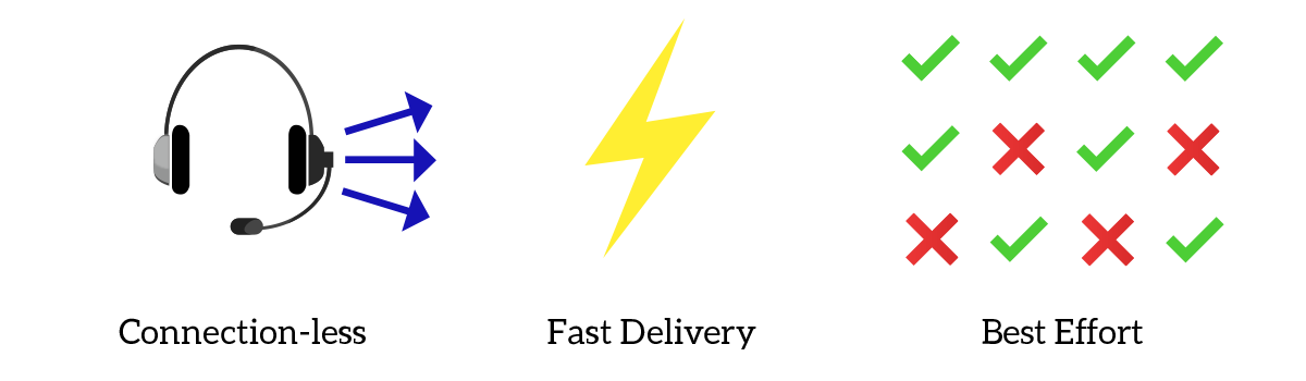
UDP is a connection-less protocol, and this mean that data can be sent straight away: there is no need to establish a connection before data can be sent, instead an application can simply choose to send data immediately. It is a fast protocol, allowing more data to be sent with a single segment if compared to TCP, and it works in best effort: this means that there is no built-in mechanism to verify that segments were received, they are just sent hoping that they won’t be lost. This also implies the lack of ordered delivery. In case we want to use UDP to have reliable and/or ordered delivery, we had to implement these features at the application layer.
UDP Header
UDP is not so complex as TCP, and there are no complex algorithms running on computers using this protocol. Check out its header to find out how simple it is.
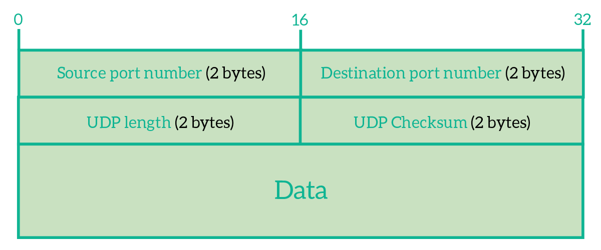
As you can see, the UDP header has just the information that allows the delivery to the correct application. We have the source port and the destination port, we have a length field to tell the receiver how long is the segment (header and data), and we have a checksum to verify the integrity of data. More than that, source port and checksum are optional fields! Let’s say we want to use these two fields anyway, we have a header of 64 bits, which much smaller than the 160-bits long TCP header. This means that in a single segment we can send 96 bits more of data with UDP than with TCP: this allows more data to be sent in a single segment and, therefore, the protocol to be faster.
At this point, you might be a little bit confused. Is it UDP better or worse than TCP? It is faster, but what happens if data are lost? That’s what the next section is for. Check that out!
UDP vs TCP
UDP is extremely faster than TCP, and not only because it sends 96 bytes more in every segment, but also because there is no connection establishment and the sender does not have to wait for acknowledgments. It is a protocol that truly works at the Transport layer, because re-transmission and ordered delivery should be tasks managed at the session layer (which TCP covers too). By having a light-weight protocol at the transport layer, we can then decide which other extra features to implement within the application, as in the following picture.
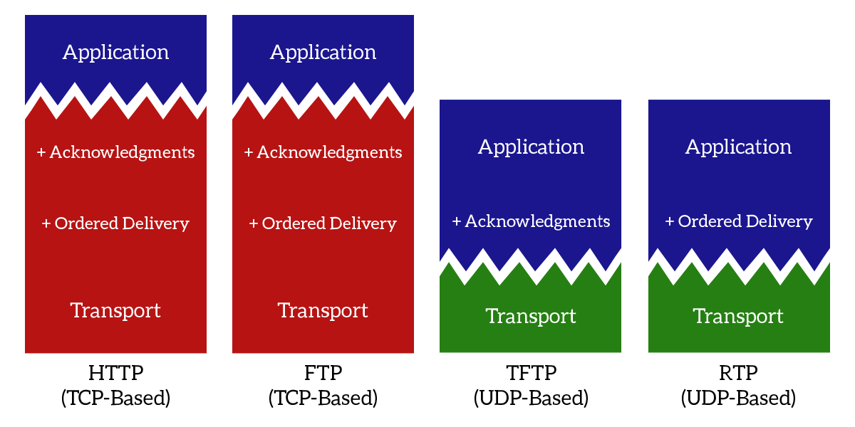
As you can see from the picture, with TCP all the session layer features are always implemented. Instead, using TCP, we can select which features to implement based on our needs. For example, Trivial File Transfer Protocol (TFTP) requires the acknowledgment of data received, while Real-Time Protocol (RTP) requires ordered delivery.
UDP is today mainly used for real-time application, with RTP sitting on top of it at the session layer. This is because real-time applications (video and/or audio streams) need speed (otherwise they wouldn’t be real-time!) and ordered delivery if possible: this means that if they receive two segments almost at the same time, they have to know which one has to go first, but in case they do not receive something, there is no time to arrange retransmission, the stream must continue (this is why sometimes you may hear disruption in a VoIP call). Because of its simplicity and extensibility, UDP is being considered a great protocol to replace TCP in the future, but for now, these ideas remain only theories and studies.
With this article, you now understand how the transport layer works, and you are ready to dive into TCP and then into session and presentation layers, as these will be the topics for the next articles in the CCNA course series.


10 Responses
Congrats man. Very usefull article 🙂
Thanks a lot!
Any feedback is welcome, and if you want to deepen some topics just let me know 🙂
Well and thoroughly explained. Thanks a lot man.
Thanks to you man, I’m happy to help 🙂
Great Mr. Alessandro. One of the best on internet and best among free tutorials.
Thanks Adeesha, I am glad you enjoyed this tutorial. I wish you all the best, and I hope the content of this website will help you accomplish your goals.
Kudos to you man. This kind of explanation is exactly what I was looking out for. Keep doing the good job. 🙂
I will keep going, there are some great articles coming! Thank you 🙂
Thanks to you I have finally understood the OSI model to a degree I just couldn’t before. Thanks again.
I just have few questions on TCP sockets and ports. How does bi directional communication through sockets take place when a device is behind NAT? and if there are only 64K ports, is that the limit of the number of connections a client can make simultaneously? (I read an answer regarding this on stackoverflow but I didn’t understand. The answer said each socket is identified by the tuple-source and destination ip and port, so there can be connections greater than 64k. But each new connection spawns a new socket with a new port. So I assume there cannot be more than 64k simulataneous connections. But I know I am wrong somewhere).
If u find that answers to my questions are going to be too long, just point to some resources which explain these concepts in a way I can understand. Thanks ?
Thank you, reading this kind of comment is a delightment.
If you are interested in how the communication works behind NAT, just check out my article on NAT. Basically the device performing the NAT keeps a special table (the “NAT table”) that associates original source and destination IPs and ports with after-NAT source and destination IPs and ports. This way, the communication is transparent to the client.
Regarding the number of connections, a connection is a identified by a pair of sockets. Since a socket is the combination of IP and port, the communication is identified by source IP and source port together with destination IP and destination port. Thus, the limit is not 64k. 64k is the limit of simultaneous connections between two IPs.
I hope you found this comment helpful, and if you need more information feel free to ask 🙂
Comments are closed.